Overview#
As the name suggests, this is how I think I (probably) understood what is the difference between a network Switch and a network Bridge.
The question arised when across a whole semester of “studying” networking at school, we never mentionned a network bridge but rather focus on routers on L3 and switches on L2 which made me think why? Are bridges now considered legacy systems? Are they the same thing? What the fuck is a bridge anyways? And what the fuck is a switch for that matter?
As a conclusion for the whole thing, I think the Friederich Nietzsche quote perfectly fits in the story.
Get Out!
Glossary#
Some terms will show up often. Although we’re not using to it as non-networking engineers, we can pick it up quickly.
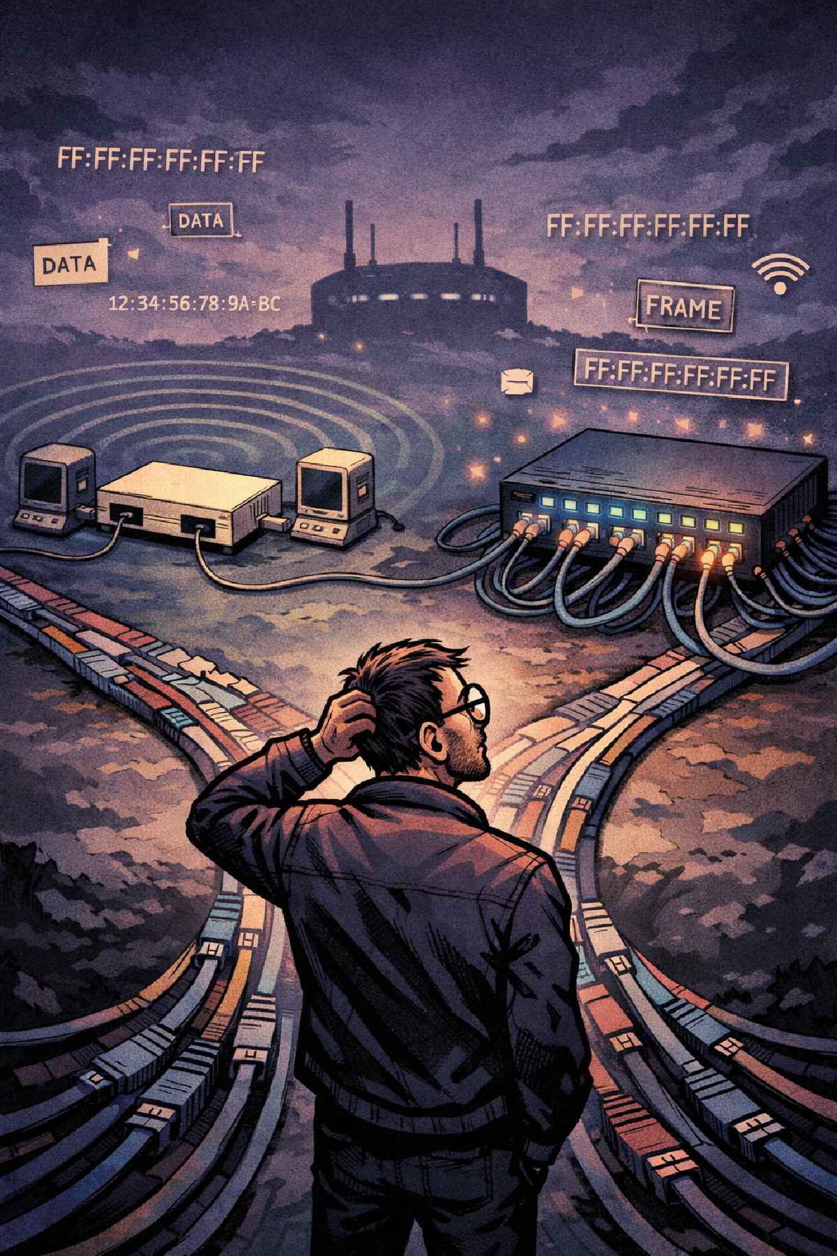
Network Link: A network link is a physical and logical communication medium that interconnects multiple network nodes using the same link-layer protocol. All nodes on a network link can communicate directly at the data link layer without passing through a router.
Network Segment: Not a one-for-all definition, but we can say it’s a portion of our network.
L1 Segment: A network segment formed by two or more connected devices on the physical layer by an electrical/optical medium.
L2 Segment: Multiple L1 segments connected via a shared
switch/bridge. This is the base of more advanced implementations of L2 segments to formVLANsandVXLANs. Communication between nodes can be done viaBroadcastingorUnicastingusing the theirMACAddresses.L3 Segment: Multiple L2 segments connected via a
router.
Broadcast Domain:
Collision Domain: Simply, it’s a network segment where simultaneous data transmissions collide with one another. Their borders were defined by bridges(we’ll see the difference between
switchesandbridges)
A bit of L1: Physical Layer#
Collision Domains#
A collision is the possibility that transmitted signals on the same hub collide with each other. Back in the day since nodes were connected to the same Hub and only one device can transmit at a time, the problem used to happen a lot.
So a collision domain is the set of devices that tend to have collision happening.
A bit of L2: Data-Link Layer#
L2 segments are a collection of L1 segments interconnected with a shared switch/bridge.
We can connect multiple switches together to create a bigger L2 segment. This “architecture” can be looked at as an upper-layer switch that connects the first L2 segment to the other.
Communication within L2 segment#
If we assume L1 is about physical connectivity between nodes, L2 represents the logical equivalent.
Communication in this layer is done via:
- The source/destination
MACaddresses. - Broadcasting using
ff:ff:ff:ff:ff:ffto the whole segment.
L2 Ethernet Frame Structure#

Broadcast Domains: One for All#
The collection of nodes that reach each other using L2 Broadcast address ff:ff:ff:ff:ff:ff. Although this is a caracteristic of L2, it is (of course) used by higher levels.
Broadcast domains are limited by routers NOT SWITCHES. So in a network with multiple switches and a router form the same broadcast domain.
Intuitively, one might think that increasing broadcast domains increases collision domains, thus worse networks. This is of course valid, until we created transparent bridges which are devices that link and transmit the frames between L2 nodes while they’re unaware of their existence.
1 Port => Point-to-Point => A single collision domain for each connection, which means no collision => A single extended Broadcast Domain.
graph TD
    A[Start] --> B[Process]
B --> C[End]VLANs: Divide and Conqueror#
So, we know LANs and LAN parties. We gather, connect our computers and then launch Counter Strike 1.6. For as much as I want to continue talking about Counter Strike 1.6, but I must go on.
VLAN is the answer to the question: What if we want to divide our L2 broadcast domain into smaller L2 domains?
VLANs allow us to keep nodes logically seperated but physically connected to the same bridge.
So while a bridge functionality is merging multiple L2 segments into one, VLANs do the opposite to get a logically seperated L2 segments.
VLAN Tagging: A look into VLAN Ethernet Frame#
VLANs are created by tagging Ethernet Frames with a 4 bytes ID that is injected within the Ethernet Frame right after the Destination and Source addresses.
That’s how VLANs are created and how we can finally obtain multiple segreggated L2 segments within a single Broadcast Domain.
Enough of Layer 2 (not really). Let’s move on.
A bit of L3: Network Layer#
We’ve seen that with L2 Layer, nodes communicate via their MAC addresses through bridges/switches. L2 is caracterized with broadcast domains and the ability to communicate to the whole broadcast domain. But that’s isn’t the case for L3. So how is communication done?
L3 Segment#
As it is the case with L2 segment, an L3 segment defined by L3 boundaries where devices communicate using routing rather than switching.
L3 Communication#
Within an L3 segment#
That being said, sending an L3 packet is simply sending the IP packet within an L2 frame to the destination IP of the L2 segment.
When arriving, the receiving node should be aware of how to translate that IP to a MAC address using Neighbor Discovery Protocol (ARP for IPv4 and NDP for IPv6).
If the translation fails, the node sends an L2 broadcast frame with a query like who is 10.10.10.10 expecting an L2 response with the destination’s node MAC address to continue the sending process.
OSI model.Across L3 segments#
Since we have more than one L3 segment, we need a router. The same logic from above applies here. The only difference is that the IP packet is sent to the gateway of the segment the sending node belongs to, which will then handle its forwarding to the destination.
All nodes should have their routing tables, which is a whole topic in itself.
Note that when a router receives the frame, it unwraps it and sends the underlying IP packet to the next-hop router.
In comparaison to the case in which the destination is in the same L2 segment, sending a L3 packet across L3 segments is like forwarding the packet to the next-hop router, until it reaches an L2 segment the final destination is connected to.
L3 Packet Structure#
VXLAN: A layer 2 that needs Layer 3#
We’ve seen VLAN, a way that allows to divide a single L2 braodcast domain into smaller ones, thus having the overlaying character.
VXLAN on the other hand is also an L2 protocol but that needs all nodes to have IP addresses (L3). It allows us to relate multiple nodes from different L2 braodcast domains into one. Thus being exactly the opposite objective of VLAN.
VXLAN allows us to connect multiple nodes across L3 segments into one virtual L2 segment, thus it is a much more powerful tehcnology than VLAN.
VXLAN Frame#
Bridge vs Switch: A Historical Confusion#
Across all the courses, LLM discussions, the term bridge and switch were used interchangibly which caused a great confusion. Are they the same thing? aren’t they both L2 ? Why are we not configuring a bridge in HUawei eNSP or Cisco’s packet tracer? Why is L2 only discussed as a transparent organ and focus directly on routing and protocols on the routers.
History#
Turns out that we started out with network devices to bridge two L1 nodes to form an L2 segment thus the name network bridge. A bridge back in the day had only 2 ports to connect two nodes and do its job.
So we have a functionality: Multiple nodes that need to be connected. Keep that in mind.
With tehcnology advancing and improving, the bridging functionality is passed on the network switch. It is a much powerful device, that, among many other functionalities, bridges multiple L2 nodes (or L1 nodes to form an L2 brodcast domain).